This is the most simple FM transmitter circuit diagram you can ever find. This circuit is really cool and cheap to build.
This FM transmitter circuit runs at low voltage, on a CR2025 3V Lithium battery, current consumption is also low.
And the total size of this F.M transmitter(including battery, excluding antenna) is less than that of a matchbox.
Simple FM transmitter circuit diagram
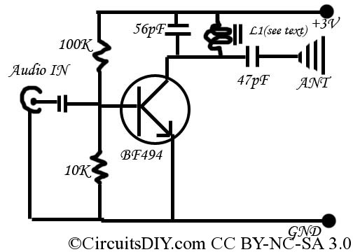
The circuit has a central RF oscillator NPN transistor BF494 (substitute: BF194). A coil takes care of the output frequency. The coil has to made by yourself. 36 SWG wire 2.5turns only in 5mm diameter ferrite rod.
Keep the circuit as small as possible. Try to use no wire in the main functional area(transistor and coil).
The input from the audio output of computer/PMP/mobile is given to the biased base of the transistor. The transistor gives a RF humming accordingly to the audio input, and the FM wave is spread by the external antenna(Ariel).
By using a standard T.V antenna, the range of this transmitter can go upto 1KM radius, using small(15-20cm) Ariel, it can work upto around 50M range. For even more low cost, use a new bicycle spoke for ariel, get it from cycle store at Rs 2/- .
This circuit is most suitable for miniature FM transmitter for use in computer, mobile etc to send music to home theater system without wires, and in homemade wireless walky-talkies.
For input from low power output devices, such as mobile, computer’s sound card, the value of the unlabeled capacitor is 0.1 or 104. For higher wattage outputs, the value is 0.01 or 103. You can add a microphone pre-amplifier in this circuit to transmit voice directly.
Keep in mind that this type of simple FM transmitter circuit are allowed for personal use. Commercial use of Radio frequencies (including FM) without permission is illegal in almost everywhere of the world.
Part list
- Transistor BF494 x1 3/-
- Resistor of various value(all 1/4 watt) x4 1/-
- Capacitor of various value(all 10V, small, ceramic) x3 2/-
- 36 SWG copper wire for coil 1 inch 1/-
Total 7/-
Others:
- input audio jack x1 3/-
- Ariel(stick antenna) x1 15/-
- Battery CR2025 x1 7/-
Cost in USD is, 0.2$
arup, how can i use C331 transistor to build a simple fm transmitter?, is it possible? Pliz help me
hi arup, what is the maximum range or power to allowe to transmit in india ?
Arup Da,
Ei circuit er broadcast ki kono car er fm receiver dhorte parbe??
Parbe boiki.
Does this circuit work???
Yes.
can you show USB powered fm transmitter
This can be USB powered, just give 5 of USB instead of 3V.
Etar range koto hobe.???
chhoto ariel diye minimum 50 metre paowa jabe faka jaygay.
plz tell any induction transmitter or oscillator which produce 2000-5000 hz frequency range upto one meter. plz tell me.
Hey Arup, great work on this one. I have couple of questions, if you mind.
Can I use condenser mic instead of Jack audio input?
And Could you please send me a formula to calculate frequency from inductance?
Thanks for your help.
For using condenser mic, you need to add an preamplifier so that the signals from the mic can be strong enough to drive this transmitter.
And how to calculate frequency?
mobile wala radio b transmiter ka signal catch karay ga? is transmitter ke frequency kitne hai? Aur kaya Audio par siraf MIC lagana hai ya Mic ka pora circuit bana kar sath wire connect karne hain
this needs better lc stabilisation cuz it jams the whole FM from sw1 to uhf
True said.
hi martin, thanks for that comment, that's exactly what I was looking for! 🙂
thx arup for your work!!!
Mobile ka mike thik rahega audio input ke lie
Yes. it will be suitable.
use 2n3904 as a transistor
Hi there.
I tried to build it with 2n3904.
Nearly not working, only very very weak signal.
I used 3.2V from USB sound module.
Also I use 30pF + 40pF trimmer. When I adjust it, I get a transient signal, about 1 KHz.
And very very weak sound transmission. Adjusting the coil makes only little difference.
2n3904 is a general purpose amplifier, and BF494 is for radio frequencies.
Look at the datasheets man.
ok arup ur correct
kya isi circut ko do ya teen stage me jodkar range badhayi ja skti ?jaise is circut me jaha output hai use isi tareh ke circut me input wali jageh me jod kar signal emplifai kar sakte ha
No
How about maximum power consumption?
I didn't calculated this, and now I don't have the unit nearby me so I am unable to give you any idea on this.
Hey ARUP,
I was searching for FM transmitter for my final year project and stumbled upon your site. What we are actually building is a FM TRANSMITTER which receives input via Bluetooth, so I was wondering will this circuit work with that configuration and if possible it would be great if you could provide the detailed working i.e. how does this circuit works.
Please reply ASAP.
I have to submit my project 1st part building a FM transmitter and I have decided that I would be using your circuit.
Please please provide the functioning of this circuit and how you designed it.
It's really very imp for my career .
Regards
kartik