This is V2 update of Atmega8 Volt-Ammeter. This new version features the following upgrades,
- Low power consumption
- Better Amperes display resolution while using low value drop resistor.
- Much smaller PCB size, only 5cm x 5cm. Still no SMD components.
- Easy calibration, only one voltage adjust and one ampere adjust preset, no voltage out detection.
| Atmega8 based Voltmeter Ammeter v2 used Component List: |
| 1x Atmega8L/Atmega8A Pre-Programmed microcontroller (PDIP) 1x 1×16 LCD with Green/Blue Backlight 1x Custom PCB (5cm x 5xm) 1x LM7805 5V Voltage Regulator 2x 22uF 50V Electrolytic polarized capacitor 1x 100kpF Ceramic Capacitor 2x 10K Multiturn Trimmer Potentiometer in 3268 package 1x 10K 1/4watt Metal Film Resistor +-5% (brown, black, orange, golden) 2x 1K 1/4watt Metal Film Resistor +-5% (brown, black, red, golden) 1x 0.1~0.5Ohm / 3W Power Resistor 1x 1x16 and 1x 1x6 female pin header for LCD and ISP |
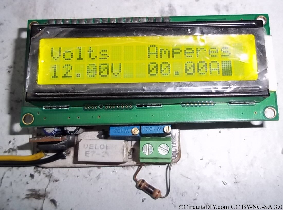
| Voltmeter Ammeter v2 Technical Specifications: |
| Voltage Supply: 6V – 30V Current Consumption: ~ 30mA with LCD backlight Voltage Input: 6-30V Voltage Resolution: 50mV Current Input: 0-5A Current Resolution: 100mA |
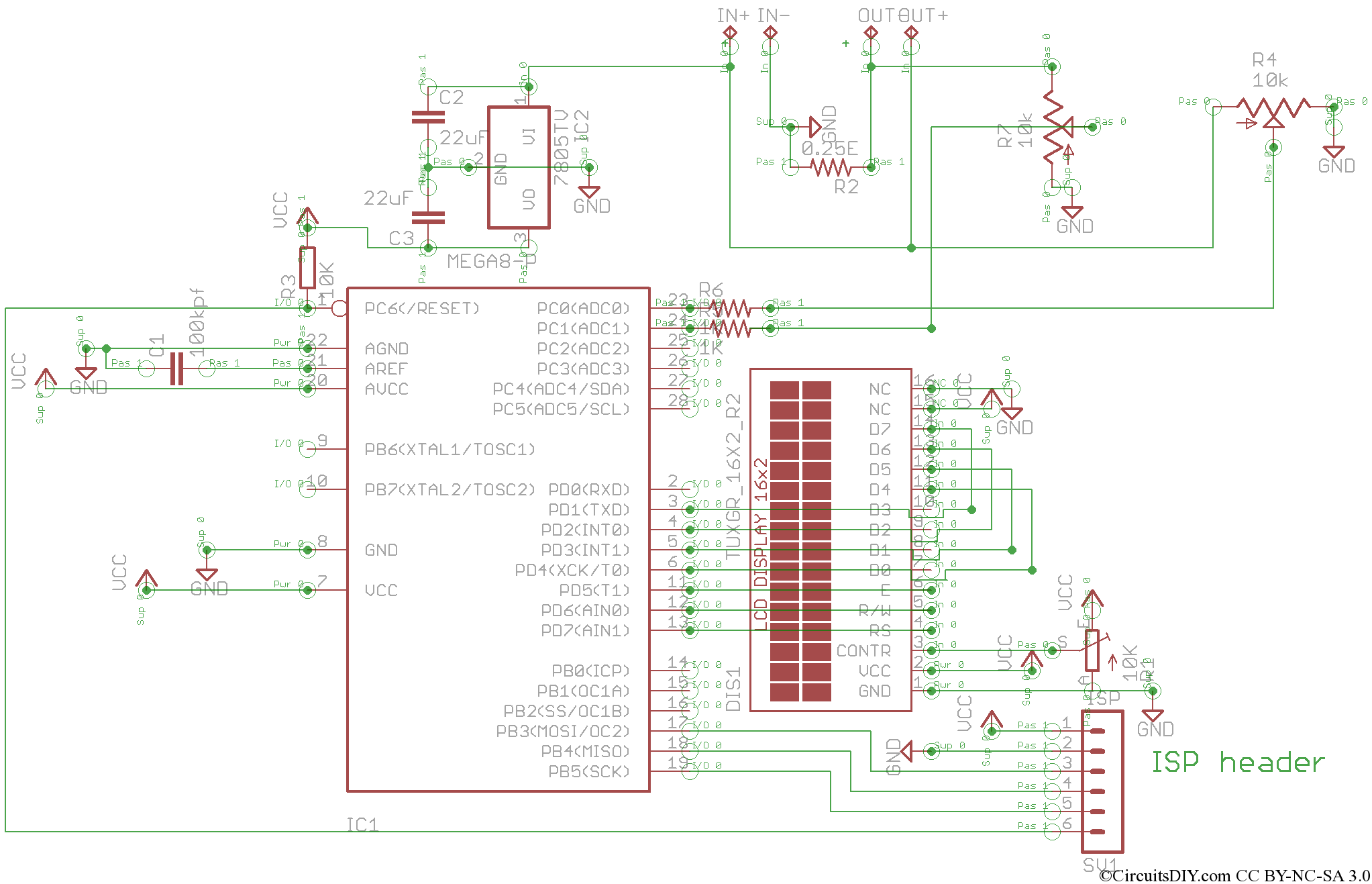
Schematics diagram
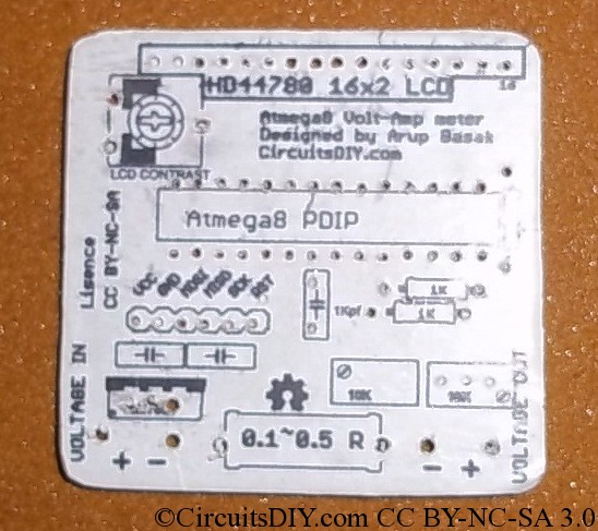
Board Top
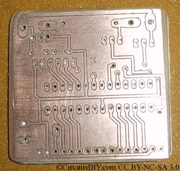
Board Bottom
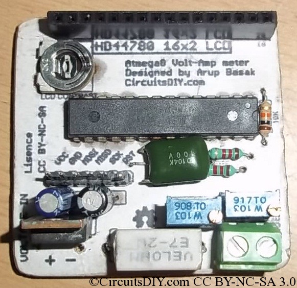
Assembled PCB
Voltage supplied by my 12Volt benchtop PSU(The resistor at output terminal is disconnected)
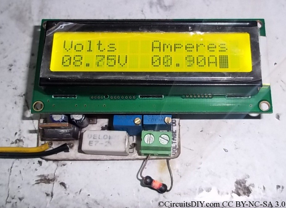
The 10Ohm resistance is connected and is burning :P. Voltage dropped to 8.75~8.80V and hence Amperes would be 0.875~0.88Amps and it is displayed here as 0.90Amps. It's perfect as the meter is having 100mA resolution.
Callibration and usage:
- Connect a 5V DC supply to the voltage input. And short pin 1 and pin 3 of the LM7805 regulator.
- Now tune the rightmost preset to show 5.00V on the LCD.
- Now connect any real power supply of say 12volts. Connect a load at output, say a auto lamp, Measure current with multimeter, or calculate Amperes, and then tune the 2nd rightmost preset to show that reading of Amperes on LCD.
Software is written in WinAVR and Peter's LCD library is used.The code below,
#include <avr/io.h>
#include “lcd.h”
#include <util/delay.h>
void InitADC()
{
ADMUX=(1<<REFS0);                         // For Aref=AVcc;
ADCSRA=(1<<ADEN)|(1<<ADPS2)|(1<<ADPS1)|(1<<ADPS0); //Prescalar div factor =128
}
uint16_t ReadADC(uint8_t ch)
{
ch=ch&0b00000111;
ADMUX|=ch;
ADCSRA|=(1<<ADSC);
while(!(ADCSRA & (1<<ADIF)));
ADCSRA|=(1<<ADIF);
return(ADC);
}
void print(uint16_t parameter)
{
parameter%=10000;
lcd_putc((parameter/1000)+48);
parameter%=1000;
lcd_putc((parameter/100)+48);
parameter%=100;
lcd_puts(“.”);
lcd_putc((parameter/10)+48);
lcd_putc((parameter%10)+48);
}
void main()
{
int adc;
while(1)
{
lcd_init(LCD_DISP_ON);
lcd_clrscr();
lcd_gotoxy(0,0);
lcd_puts(“Volts”);
lcd_gotoxy(8,0);
lcd_puts(“Amperes”);
lcd_gotoxy(0,1);
InitADC();
adc=ReadADC(0);
print(adc*5);
lcd_puts(“V”);
InitADC();
adc=ReadADC(1);
lcd_gotoxy(8,1);
print(adc*10);
lcd_puts(“A”);
_delay_ms(100);
}
}
Downloads:
UPDATE:- The previously uploaded compiled HEX file had some problems. Use this hex file with fuse settings.
-U lfuse:w:0xe1:m -U hfuse:w:0xd9:m
Where can I found HEX file for Atmega8?
Is this version for solar charging panel? Probably no, I need measure power of battery and current cca 5A max, and information when battery is in charging or discharging.tnx for info st.
Download the project package. You'll get the .HEX file there.
sir i need this full project for my project completion thanks in advance.
in this part
lcd_putc((parameter/1000)+48);
why are all these 48 added?
also
ch=ch&0b00000111; why this line? 'ch' is then ORed to the ADMUX register, but for a PDIP ATmega8, there are only 6 ADC inputs (ADC0 to ADC5), so max values for MUX3..0 registers can be 0101 which is binary for 5, thus selecting ADC5.
The lcd_putc() function prints the parameter value in the LCD in ASCII format. To print digits, the (0-9) series starts from 48 in ASCII format. That's why 48 is added to every number that is to be printed.
The makefile and everything is made according to atmega8. in atmega8 SMD version there exists 8 ADC inputs. That's why ch is ANDed with 0x07 to get the ch in 0-7 range for selecting ADMUX.
Hello!
First of all, thanks for publicing this project with all files!
I've a question though, I wan't to be able to measure 1.2-12V. I guess the limitation for at least 6V in your project is because you supply the atmega8 thru Vin? So my question is: if I supply the atmega8 separated from meusuring voltage (by connecting for example 7V directly to voltage input for the 7805 and don't connect it to Vin) will this circuit be able to measuring my 1.2-12V?
I would also be grateful if you could describe how the measuring part of the circiut actually works. Otherwise KEEP UP THAT GOOD WORK!
Yes you can separate the Vin from 7805's input and can measure from minimum 0V in the circuit.
Thanks for your answer.
I've another question: what function does the low ohm power resistor have?
It drops a very little voltage which is proportional to the load current, and the load current is measured by the voltage drop.
which fuses should we select when programming the atmega?
No fuse-editing necessary. This works on the factory preset fuses.
Witch program schould I use for programming?
I have a simple ISP programmer, and I want to use ponyprog for programming.
I have been tryed to do with these with factory default fuse bits, but the LCD didnt show nothing.
Thank You for youre help!
Try the patch Rohit Soni tried below.
plz help circuit isn't working. no lcd display.. tried multiple times by changing lcd, controller . pcb is same as shown . hex file is same as main.hex
1. Check connections to every LCD pin from microcontroller by using multimeter.
2. Verify the 5V supply.
3. Verify that the microcontroller is running at 1Mhz with default fuse settings.
i verified it all. controller's fuse bit are set for 1 mhz. 5v supply is constant for controller and lcd. checked all.
i tried this program on development board too but it didn't worked.
please provide me a diifferent hex file if any
Good advice: Make the v1 first on breadboard.
Quack treatment: Power on this board, then insert LCD and then reset the MCU.
i just did 1 thing. i just connected the controller, reset ckt,and lcd on breadboard. but it didn't worked.controller is well programmed as verification was sucessfull.
Something must be wrong. Did you adjusted the contrast of LCD correctly? Else nothing will appear on LCD.
ya i did that all.. still no success
quack treatment worked for me.. but each time doing all this is a big problem.. any solution for this??
thanks arup...
The version3 coming soon.
PCB lungs shook off the possibility to send with PDF files is? Thanks
ver3 with pcb pile together Expects Thanks Far from Korea
nice share... thanks a lot... useful for building my project, magnetic levitation and its controller.. from Indonesia... 🙂
Hello Arup!
I'm not able to open your Project Package. When I extract zip-file, so I see only a strange file without any file extension. Only "software" and nothing at the end... What does it mean? Could you tell me, which editor can open it?
Best regards, Art
LOL, it's a directory named software. You need to enter the directory and there you'll find files.
Hi Arup! Maybe it sounds silly, but tell me please, how should I enter this directory??? I see only "software" without any extension and program on my PC can open it... 🙁
I mean no program can open it........
Use 7-zip or G-zip instead.
Hi Arup
Nice project, how is v3 coming along?
I have got mine running but only if I reset the MCU each time, not really practical for my application,hope you can get a fix for it 🙂
Other problem is the LCD reading 51.5 volt and does not respond to ajustment of trim pot?? any ideas??
Cheers from New Zealand
Thanks for leaving a comment from far NZ.
I'll work on v3 software after my next exams, (say sept), so I can't give you any better news as for now.
hai, i want to buy this kit can you help in this.../
Version3 design complete. Will be for sale after a month. Please wait till then.
good project
how much voltage and current it able to measure ?
DEAR SIR
I TRIED TO SIMULATE YOUR HEX FILE USING PIC SIMULATOR, BUT I AM GETTING A ERROR MESSABE
CNA YOU HEALP ME ?
It's on AVR mcu and not on PIC mcu.
Hi there,
Great job with this project! I'd like to make one meter for my PSU, but I can't decode value of capacitor between ARef and AGND: in your part list there is 100kpf - what does that letter k mean? I've never seen such mark, neither in EU or US symbols. Or maybe it's just a typo and the proper value is 100pF (one hundred picofarad)?
Thanks in advance,
Regards, nemo
By 100kpf, I meant 100-kilo-picofarad that is 100nF.