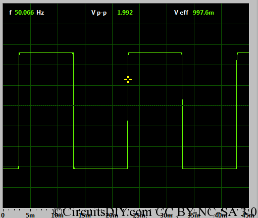
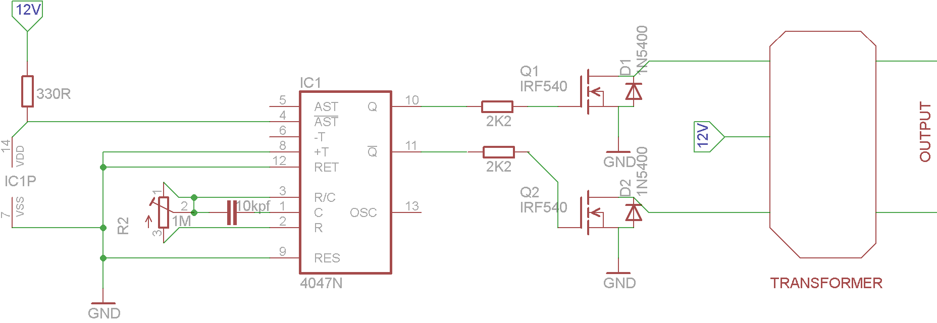
This is a basic square-wave oscillator based inverter kit. Based on the 4047 I.C oscillator, we discussed here, it is a finalized PCB version of that inverter with MOSFETs.
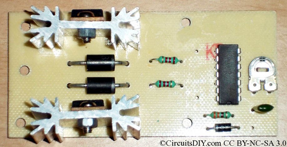
Here are two MOSFETs, one for each channel and this board consists of reverse diodes in MOSFET section for battery charging support. With FB4710 or P55NF06 or IRFZ44 or IRF540 MOSFET, we can get output power of 150VA, 180VA, 220VA, and 100VA.
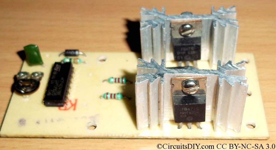
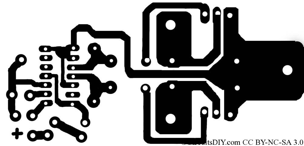
The setup is simple, just download the 300dpi non-reflected PCB layout from below, and place components as you see in the above images.
I’m not going to give you headache of complex circuit now, just follow what you see in images, and if you have comments/questions, ask them below in comments section.
Parts List:
- I.C HCF4047BE 1p
- Capacitor 0.01uF or 103 1p
- Potentiometer 1mega 1p
- Diodes 1N5408 2p
- Diode IN4007 1p
- Resistor 2.2K 2p
- Resistor 330E 1p
- MOSFET (any from list) 2p
- Heatsink of TO-220 2p
Note: PCB size is 8.5 cm x 4 cm. To make the PCB, follow guidelines here.
Please provie the circuit diagram. if possible mail the documents if available.
thanks,
bharadwaj
Yes...Admin
Please provide us the circuit diagram..otherwise it is very difficult to make this circuit.
It's so clear image that you can easily make the board and place3 components as in the image. If you need circuit diagram, have a look at the link in the 2nd line of this article.
I need 200VA Inverter and solar charge controller can u guide me my cont:
Give the output transformer design for this kit.
hai ARUP , congratulations for your great work.i'm seeing this for 1st time. in this ckt where to connect battery and power source. pls reply
Take a look at "CD4047 based Squarewave Inverter Oscillator" for details.
hi...arup. i am fist time build pwm for the DC motor . I use mosfet FQP80N06 in pwm that mosfet can handle max current 80amp . but when connect pwm to motor with load ,the max pwm controll current only 2amp . if i direct connect the 12vdc to the motor the amp meter show 20amp can reach .. my pwm can control the Volt gate mosfet from 0-9.4 vdc..what problem with my pwm only can controll 2amp ??
Check if saturating MOSFET's gate terminal makes 20Amps of current or not.
Sir, can fix it in 60 hz with out potentiometer? what value of resistor to be replace in potentiometer to fix it in 60 hz.thanks and more power.
In astable mode, the calculation is done by T=4.40 RC.
For F=60Hz, T=1/60 ~ 16.7ms. If you use 10kpf(103) capacitor, then R becomes 3787Ohm.
I have made a dc to dc convertor circuit by using sg3525 ic and two p55nf06 transisters. In the circuit 12v dc converted to ac by p55nf06 and ac voltage increase by 5a transformer then the increased ac convert by 5408 diode.I was geting 60v dc But my requirement is to use a ac home theatre by dc.The home theatre have step down transformer 250v to 14.Phase wire connected to two diode(p&n) the two diodes gone through two branch,nutre directly connected to the board. Please help to solve the problem
I am not understanding your concern. Please explain.
I want to make 14v Ac at 3A from 12v Dc .Can I possible to make above by sg3525 ic and two p55nf06 transisters?
You need a transformer too for that approach.
Instead use a step up voltage converter to get 14V from 12V.
If you possible to give a circuit diagram for that,please give
Will update in a day. Keep watching.
yesterday you have told me "I need a transformer too".I have a UPS transformer.Is it enough for my need?
Circuit diagram updated.
UPS transformer is enough. Take output from the opposite 12V pins instead of taking from 230V output section.
can I able to place IRFZ44 or P55NF06 instead of IRF540?
Yes.
what will happen when square wave ac using instead of sinewave ac?
square wave possess less efficiency and some appliances don't work on square wave AC.
mr.arup,my name is ganesh from tamilnadu.i want the 1000va sinewave inverter circuit diagram and its transformer details
I have a transformer.It was dismantled for increasing the secondory turns.It having two blocks just like 'E' .And I re-arrange by insulation tap.but it not working.what was the problem?
Hi Arup,
I have designed an Inverter circuit by using only 555 Ic and IRFZ44N mosfet the output is Square wave and i have given that to 12-0-12 Transformer , but this circuit i have designed to use only for U shape power saving lamp so o/p of the transformer i am converting to DC by using 1N5408 and 1.2mF capacitor , but here i cannot able to creat 230 V by giving 50Hz O/P just randomly i was adjusting the preset and i was increasing the frequency to 2 or 3 KHz at that time i got 240V AC , but this i cannot able to use it for any equipments which are working with AC Voltage , i tried with my home theater system its working but i am getting some humming sound because of the high frequency , so is it able to trigger my MOSFET by sine wave so that some what little wave form of the transformer O/P May change to slight sine wave , so how to convert mosfet o/p to sine wave and again give it to transformer is there any way for that
Regards
Athish
Unfortunately there's no easy way to do it. Keep the 555 at 50Hz and add a capacitor in the output to smooth-en the O/P wave. This will help a bit.