An year ago, I’ve shared a circuit of USB li-ion charger based on LM358opamp. The circuit had some problems as reported by commentators that inclide wrong direction of LEDs.
Features:
- Charging via mini-USB connector which is very common.
- Charging status display by LED
- Simple circuit by using opamp, resistor, and not by any complex dedicated IC or micro-controller.
- Charges completely drained (0V) battery packs.
- Max charging current 500mA(limited by USB supply), depending on battery.
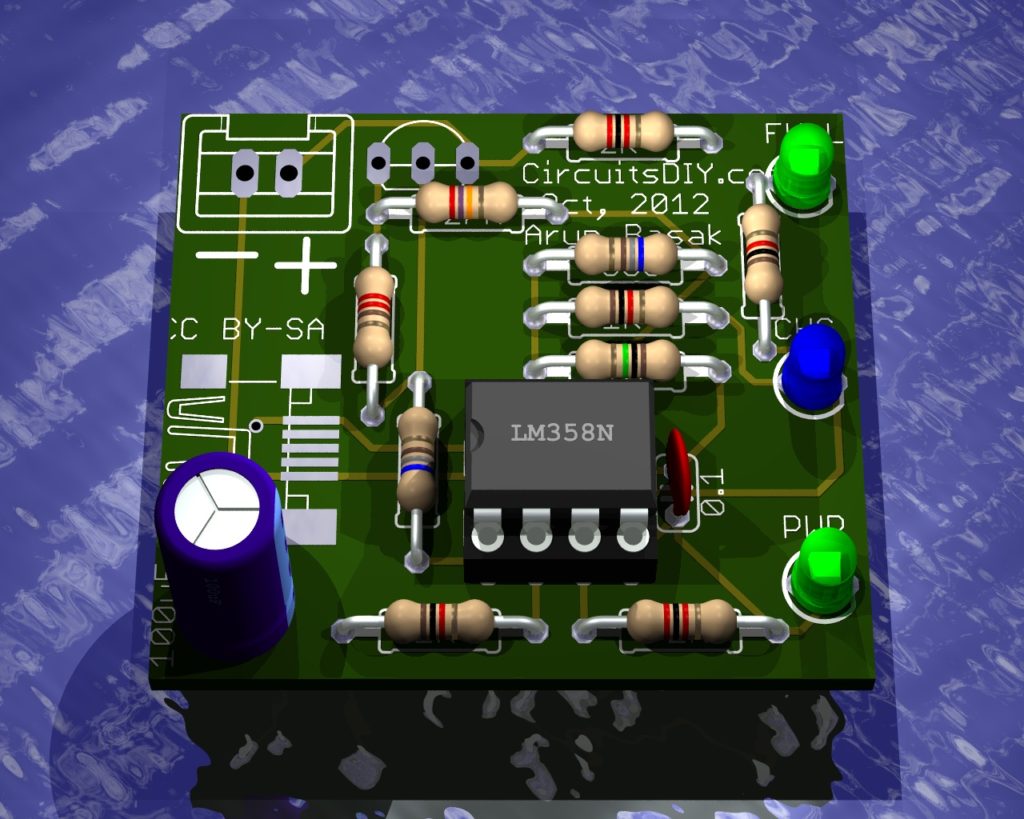
Here’s the corrected schematics and the board design of the circuit.
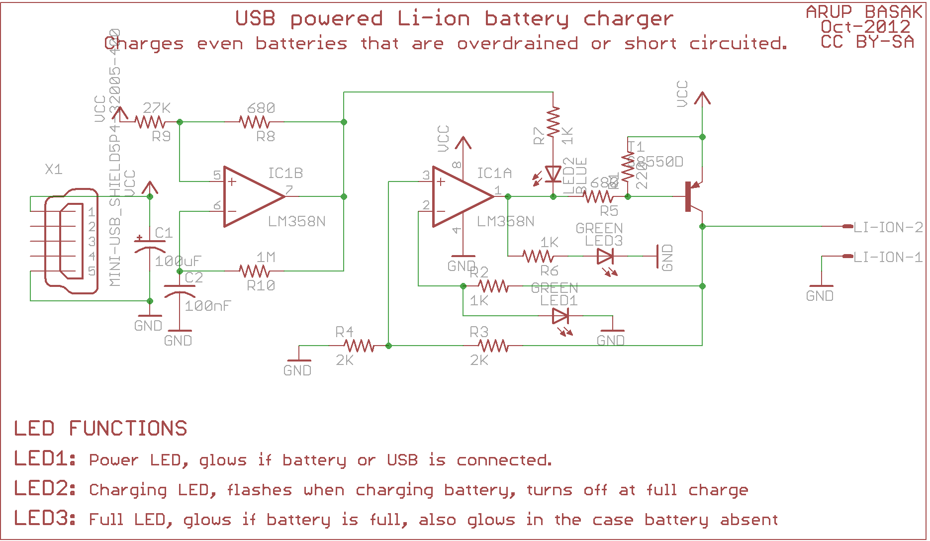

Update: https://www.circuitsdiy.com/usb-li-ion-charger-build
Boards are available for buying.


Hi again, it’s not charging properly, my batteries charged all night and didn’t stopped… when i saw, it was like 4,6v and full charging led didn’t came up… any idea? when i have the li-ion battery disconnected, the tension is 4,12v. when i connect it, the value gets down to the same as the battery and starts to charging.. but didn’t stop charging.. i just changed the r4 value, as i described up… i think i’m really close…
Pingback: USB li-ion charger built by Jamie | Cicuits DIY
hello I would like to buy your USB charger li-ion revision
I’m in Brazil, you can send to me?
thank you
Carlos.
08/20/2013
Out of curiosity, why go with both the negative and positive inputs on the collector, And not pin 2 to the collector and pin 3 to the emitter?
.
I am not bashing it because I’ve built it and it works well.
Also would it be plausable to use the pnp to switch on a darlington or other current boosting transistor. (pnp collector to npn base) . Only because the tip 102 darlington is quite common at places like radioshack..
I also added a mc34063 simple boost from 3.7 to 5.5v to a usb female jack to turn this into a sweet battery backup charger. As well as a 6v solar panel input for sunny days.
Thanks for sharing
can u explain how it works inside the circuits ?
hello i made this circuit but i got 3.7 out,i replace r3 with 2.2k and 390 ohm in series and i got 4.1 v and its working, the only problem is led2 is not blinking. anyway thank you.