This is V2 update of Atmega8 Volt-Ammeter. This new version features the following upgrades,
- Low power consumption
- Better Amperes display resolution while using low value drop resistor.
- Much smaller PCB size, only 5cm x 5cm. Still no SMD components.
- Easy calibration, only one voltage adjust and one ampere adjust preset, no voltage out detection.
| Atmega8 based Voltmeter Ammeter v2 used Component List: |
| 1x Atmega8L/Atmega8A Pre-Programmed microcontroller (PDIP) 1x 1×16 LCD with Green/Blue Backlight 1x Custom PCB (5cm x 5xm) 1x LM7805 5V Voltage Regulator 2x 22uF 50V Electrolytic polarized capacitor 1x 100kpF Ceramic Capacitor 2x 10K Multiturn Trimmer Potentiometer in 3268 package 1x 10K 1/4watt Metal Film Resistor +-5% (brown, black, orange, golden) 2x 1K 1/4watt Metal Film Resistor +-5% (brown, black, red, golden) 1x 0.1~0.5Ohm / 3W Power Resistor 1x 1×16 and 1x 1×6 female pin header for LCD and ISP |
| Voltmeter Ammeter v2 Technical Specifications: |
| Voltage Supply: 6V – 30V Current Consumption: ~ 30mA with LCD backlight Voltage Input: 6-30V Voltage Resolution: 50mV Current Input: 0-5A Current Resolution: 100mA |
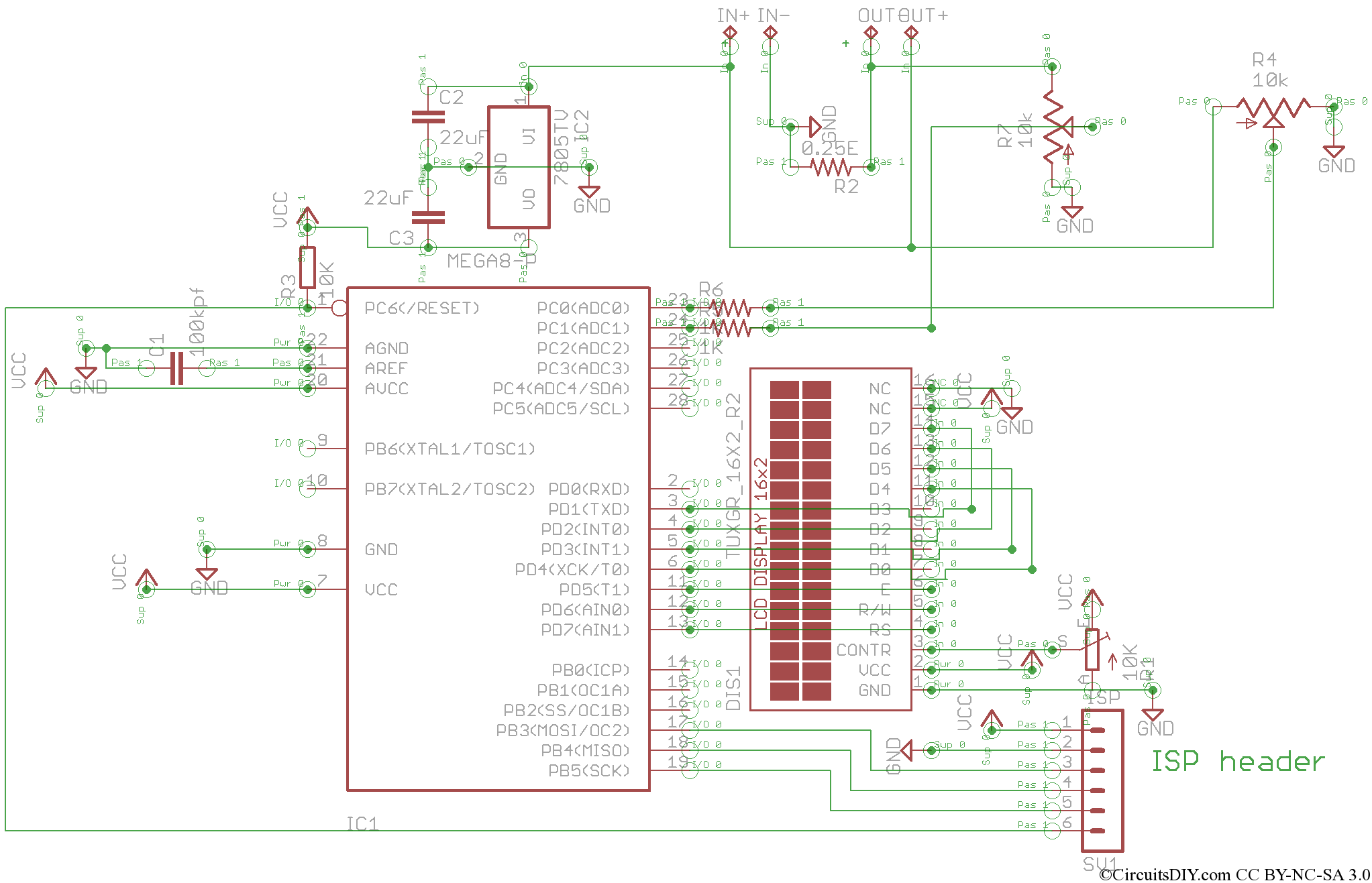
Schematics diagram
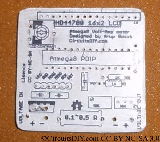
Board Top
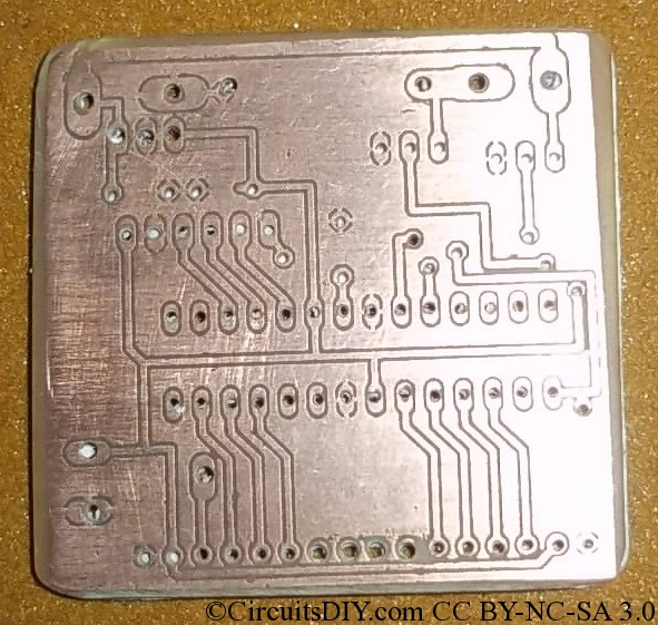
Board Bottom
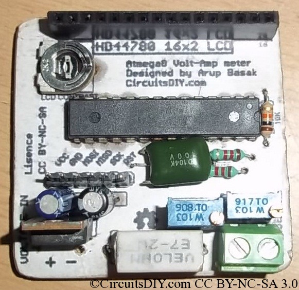
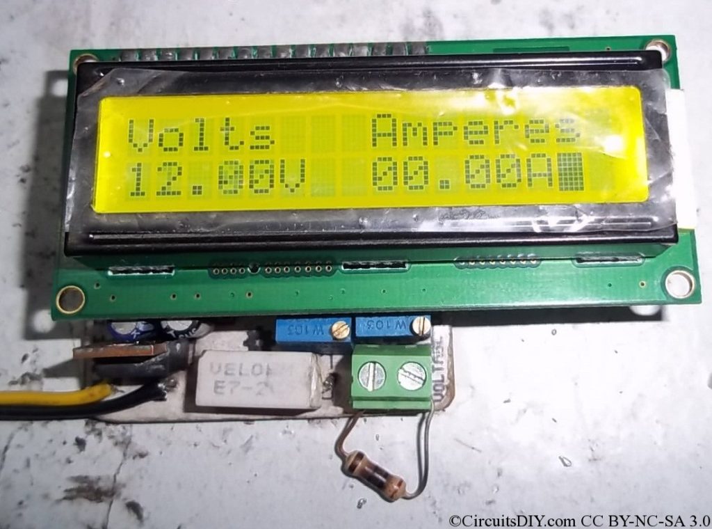
Assembled PCB

Voltage supplied by my 12Volt benchtop PSU(The resistor at output terminal is disconnected)
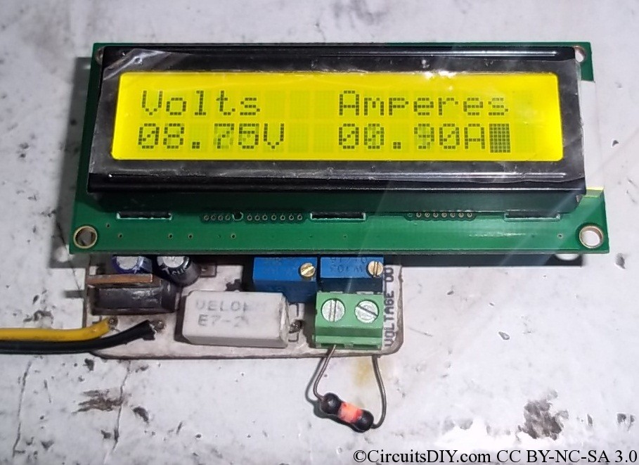
The 10Ohm resistance is connected and is burning :P. Voltage dropped to 8.75~8.80V and hence Amperes would be 0.875~0.88Amps and it is displayed here as 0.90Amps. It’s perfect as the meter is having 100mA resolution.
Callibration and usage:
- Connect a 5V DC supply to the voltage input. And short pin 1 and pin 3 of the LM7805 regulator.
- Now tune the rightmost preset to show 5.00V on the LCD.
- Now connect any real power supply of say 12volts. Connect a load at output, say a auto lamp, Measure current with multimeter, or calculate Amperes, and then tune the 2nd rightmost preset to show that reading of Amperes on LCD.
Software is written in WinAVR and Peter’s LCD library is used.The code below,
#include <avr/io.h>
#include “lcd.h”
#include <util/delay.h>
void InitADC()
{
ADMUX=(1<<REFS0);                         // For Aref=AVcc;
ADCSRA=(1<<ADEN)|(1<<ADPS2)|(1<<ADPS1)|(1<<ADPS0); //Prescalar div factor =128
}
uint16_t ReadADC(uint8_t ch)
{
ch=ch&0b00000111;
ADMUX|=ch;
ADCSRA|=(1<<ADSC);
while(!(ADCSRA & (1<<ADIF)));
ADCSRA|=(1<<ADIF);
return(ADC);
}
void print(uint16_t parameter)
{
parameter%=10000;
lcd_putc((parameter/1000)+48);
parameter%=1000;
lcd_putc((parameter/100)+48);
parameter%=100;
lcd_puts(“.”);
lcd_putc((parameter/10)+48);
lcd_putc((parameter%10)+48);
}
void main()
{
int adc;
while(1)
{
lcd_init(LCD_DISP_ON);
lcd_clrscr();
lcd_gotoxy(0,0);
lcd_puts(“Volts”);
lcd_gotoxy(8,0);
lcd_puts(“Amperes”);
lcd_gotoxy(0,1);
InitADC();
adc=ReadADC(0);
print(adc*5);
lcd_puts(“V”);
InitADC();
adc=ReadADC(1);
lcd_gotoxy(8,1);
print(adc*10);
lcd_puts(“A”);
_delay_ms(100);
}
}
Downloads:
UPDATE:- The previously uploaded compiled HEX file had some problems. Use this hex file with fuse settings.
-U lfuse:w:0xe1:m -U hfuse:w:0xd9:m


i am getting blank on display ,i checked my hard ware all are good ,give be some suggestion for burning hex ,hope some trouble in fuse settings .
can you send me HEX with Fuses settings..i use codevisionavr ….thanks
Thank you sir.
Thanks for sharing your thoughts about 1040 car donation.
Regards
Hello,
I have same problem with LCD display.
LCD init is wrong. When I plug in power on LCD display mcu, then
I see text. and then an extra MCU reset on GND.Dann I can see everything.
Udo
If I give RS LCD signal of short pulse high and then give MCU reset the software works.
Hello,
I have found the error in Maim.c. The new hex file can I send.
Who has interest. (DG9FDU@web.de)
‘ 04.08.2013
‘ Atmega 8
‘ Display mit 2×16
‘BASCOM Compiler
‘——————————————————————————
$regfile “m8def.dat” ‘Definiert den Atmega 8
$crystal = 8000000 ‘ Taktfrequenz 1 Mhz
Config Lcd = 16 * 2 ‘LCD Display in Art und Größe
Config Lcdpin = Pin , Db4 = Portd.4 , Db5 = Portd.3 , Db6 = Portd.2 , Db7 = Portd.1 , E = Portd.5 , Wr = Portd.6 , Rs = Portd.7
Dim Mess_volt As Word
Dim Mess_amper As Word
Dim Volt As Single , V As String * 10
Dim Amper As Single , A As String * 10
Dim Watt As Single , W As String * 10
Const Adc_multi = 0.0146484375 ‘0,0146484375 = 15 Volt max Messwert bei 5 Volt Referenz / 1024
Config Adc = Single , Prescaler = Auto , Reference = Avcc
Start Adc
Cls
Do
Mess_volt = Getadc(0)
Volt = Mess_volt * Adc_multi
Volt = Volt * 80
Volt = Volt / 50
Mess_amper = Getadc(1)
Amper = Mess_amper * Adc_multi
Amper = Amper * 80
Amper = Amper / 50
Watt = 0
Watt = Watt + Volt
Watt = Watt * Amper
V = Fusing(volt , “#.##”)
A = Fusing(amper , “#.##”)
W = Fusing(watt , “#.##”)
Locate 1 , 1 : Lcd “Volt ” ; V
Locate 2 , 1 : Lcd “Amper ” ; A
Wait 1
Locate 2 , 1 : Lcd “Watt ” ; W
Wait 1
Loop
Danke der Code funktioniert nach ein paar Konvertierungsfehlern. 🙂
4 my Simson: XD
$regfile = “m8def.dat”
$crystal = 8000000
$hwstack = 40
$swstack = 16
$framesize = 32
Config Lcd = 16 * 2
Config Lcdpin = Pin , Db4 = Portd.4 , Db5 = Portd.3 , Db6 = Portd.2 , Db7 = Portd.1 , E = Portd.5 , Wr = Portd.6 , Rs = Portd.7
Cursor Off
Dim Mess_volt As Word
Dim Mess_amper As Word
Dim Volt As Single , V As String * 10
Dim Amper As Single , A As String * 10
Dim Watt As Single , W As String * 10
Const Adc_multi = 0.0146484375
Config Adc = Single , Prescaler = Auto , Reference = Avcc
Start Adc
Deflcdchar 0 , 32 , 32 , 32 , 31 , 32 , 32 , 32 , 32 ‘ replace [x] with number (0-7)
Deflcdchar 1 , 32 , 16 , 8 , 4 , 2 , 1 , 32 , 32 ‘ replace [x] with number (0-7)
Deflcdchar 2 , 32 , 4 , 4 , 4 , 4 , 4 , 32 , 32 ‘ replace [x] with number (0-7)
Deflcdchar 3 , 32 , 1 , 2 , 4 , 8 , 16 , 32 , 32 ‘ replace [x] with number (0-7)
Cls
Locate 1 , 1
Lcd “V-A-W Meter 1.0”
Locate 2 , 1
Lcd “KR51/1 Vape”
Wait 1
Cls
Locate 1 , 1
Lcd “5V Switcher 2.5A”
Locate 2 , 1
Lcd “USB Charger”
Wait 1
Cls
Locate 1 , 1
Lcd “By D.R”
Locate 2 , 2
Lcd “: -) ”
Locate 2 , 1
Lcd Chr(0)
Waitms 200
Locate 2 , 1
Lcd Chr(1)
Waitms 200
Locate 2 , 1
Lcd Chr(2)
Waitms 200
Locate 2 , 1
Lcd Chr(3)
Waitms 200
Locate 2 , 1
Lcd Chr(0)
Waitms 200
Locate 2 , 1
Lcd Chr(1)
Waitms 200
Locate 2 , 1
Lcd Chr(2)
Waitms 200
Locate 2 , 1
Lcd Chr(3)
Waitms 200
Cls
Do
Mess_volt = Getadc(0)
Volt = Mess_volt * Adc_multi
Volt = Volt * 80
Volt = Volt / 50
Mess_amper = Getadc(1)
Amper = Mess_amper * Adc_multi
Amper = Amper * 80
Amper = Amper / 50
Watt = 0
Watt = Watt + Volt
Watt = Watt * Amper
V = Fusing(volt , “#.##”)
A = Fusing(amper , “#.##”)
W = Fusing(watt , “#.##”)
Locate 1 , 4 : Lcd “Volt*” ; V
Locate 2 , 4 : Lcd “Amp.*” ; A
Wait 3
Locate 2 , 4 : Lcd “Watt*” ; W
Wait 1
Loop
Hi Friend
I can do all the electronics except pic programming
pl. tel me if I copy your main.hex text to programmer software and compile
is it all about the this pic programming, what is the suitable software for this programming pl help me on this
thank you
Hay Thushara
Have you found the circuit (Atmega8 based voltmeter ammeter v2) also created and operates at you …. !!!! I have also made but I get that but not in operation, and the light definitely on the software, the circuit I’ve checked several times and it is 100% fit, like some more information, and if that works, it is possible my the good software by sending through my mael Address.
Mvg ……… Henri
Hey Henri, could you please share your working circuit diagram and C code with us ?
I’ve sent you a mail.
Hey…….
I made the Volt and ammeter ATmega8 programmed and yet it does not work, ask – is the hex file corekt or has another cause like some more information if it is possible to send me the correct hex file
Mvg ..
Thanks Henri, I apologize that I’m not the author/creator of this project, and original author is currently busy.
But from where did you got the hex file ? Is it from the Downloads section in this tutorial ?
Hay Arnab
I made the circuit as on the blog, and that’s not a problem.
I’m looking for the software (Hex file) that works, the software does not work on the blog. If I have a good HEX file and it works well, then I will confirm that with pictures.
Thanks for the replay
Mvg … Henri
Thanks ! I’m waiting for your working HEX file.
Hi Henri,
Make sure your atmega8 is tuned for internal 8Mhz oscillator.
Simply burn this fuse settings. “-U lfuse:w:0xe4:m -U hfuse:w:0xd9:m ”
Thanks and regards,
Arup
Hi Arup
THE Lfuse and Hfuse and Xtal frequency are all set correctly, the PCB layout is also correct and I program with the programmer and the programming software PonyProg, any many other circuits that I have to work flawlessly already, so I think is wrong with Hex file uploads to the site. We are sorry for this project if it can not work. Do you sometimes have the correct working hex file and please please pass it forward.
Thanks and regards,
Hey ,
yes that’s right, I made it out of that download setion and that does not work, the question is whether it is possible to send the working hex file
Thanks and regards,
Hi, I’ve recompiled the source and generated a new hex file.. Please try this…
https://drive.google.com/file/d/0B5oY8F8VOr7ic18ya1FtYVFxb1E/view?usp=sharing
Hi Arup
Thanks for forwarding the link, I’ve then downloaded but regretfully I must inform you that the new file does not work, I think there is an error in it for the gecompuleerd, has now also made the circuit and works that …
Mvg..Henri
Arup thank you for the reply …………
Hi there. If you need, I’ve uploaded a new hex file which operates at 1Mhz. Check at the end of the article. Thanks.
Hallo!
wolte das projekt nach bauen,aber die hex geht nicht?
gruß thomas
great post! thank you so much for sharing this. cheers!
I have question , I try for Voltage (Out +) it ok, but for amp (Out -), MCU cannot detect analog signal, because current go pass resistor 0.25ohm (3W) not go to Potentiometer 10K. Anyone can help me?
Note : I use resistor 0.5ohm(5W)
Hi can i use this code in arduino use? Or someone have arduino code for atmega8? Thanks in advance
Can you please repair the new hex.file link because its not working.