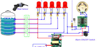
Water level indicator is a very easy electronics project. Water tank overflow as well as tank exhausting without any previous clue is a common household issue which we have to […]
Repair TP-Link TL-WR740N Router WAN port
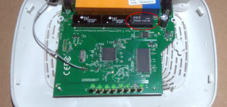
This article describes how I repaired my router which had burnt WAN port at no cost.
Reduce Refrigerator bills with this Simple circuit
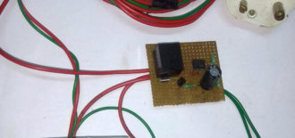
Refrigerator is a common household electrical appliance. When we buy refrigerator we try to minimize the electrical power consumption by looking for BEE 4 or 5 star rated ones which […]
Simplest shortwave transmitter circuit ever
So, if you're looking for the the simplest and cheapest shortwave transmitter circuit, it's here. This transmitter is very low power and very stable as well, uses a readily available […]
How to accurately measure low resistance with cheap Multimeter
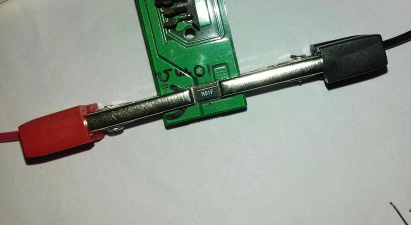
We often need some low value resistors, less than 1 Ohm. Mostly as current sensing resistors in power electronics projects. You can't measure less then 1 Ohm with cheap multimeters. […]
LM317 constant current source circuit design
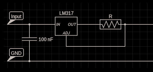
A constant current source source can supply a fixed current to a load regardless of input voltage or load change. LM317 constant current source is one of the simplest design. […]
Directly Drive LED array from 230V AC
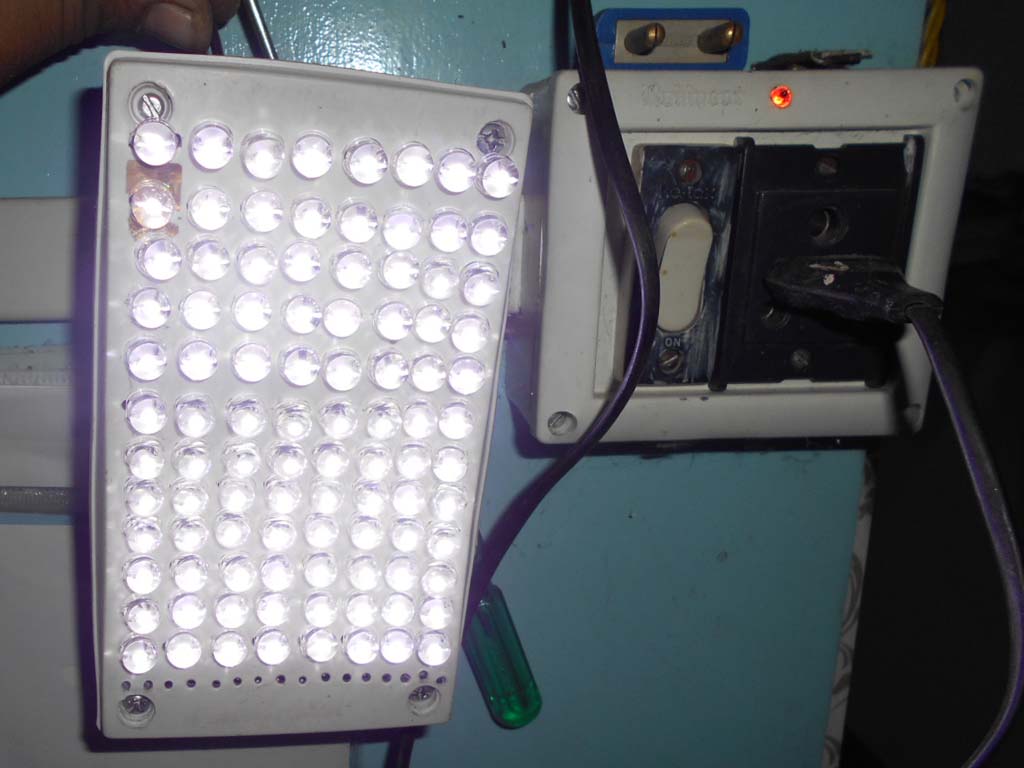
LEDs are DC devices, operating from a few volts of direct current. Where power is supplied by a DC battery like mobile phone, or torch, you can easily run LEDs. […]
What is dielectric resonator oscillator and it's application
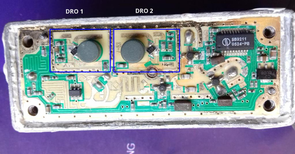
A dielectric resonator oscillator is basically a high frequency oscillator, operates within a range of few tens of gigahertz. The main frequency determining component is piece of dielectric material, usually […]
HH004F LED driver circuit
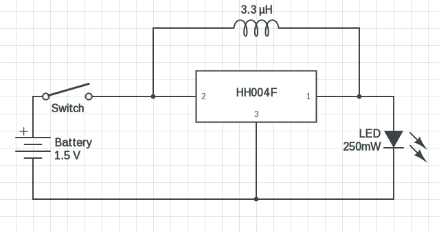
HH004F is a low power integrated boost converter IC in a TO-92 package, look exactly like a small transistor. Though it's quite a uncommon and undocumented IC, but you may […]
Free PCB design software - Ultimate list of 2018
There's no short of free PCB design software to get your very own PCB ready. But which one should you choose ? Each of them have a fairly time consuming […]
- 1
- 2
- 3
- …
- 12
- Next Page »